
H3C S5130交换机基本配置
前言:
H3C交换机基本配置
1.密码恢复:
2.划分vlan配置ip
3.acl包过滤
4.静态路由
5.ntp配置
6.snmp
7.telnet
8.ssh
9.ftp
1. 组网需求
2. 组网图
3. 配置步骤
10.lldp
11.Vpn实例
**(1)**SW1、SW2、SW3根据(图2)中的相关IP地址进行配置部署。
**(2)**SW1配置去往3.3.3.3/32网段的静态路由;SW3配置去往1.1.1.1/32网段的静态路由
**(3)**SW2在实例12中配置去往1.1.1.1/32网段的静态路由;在非实例中配置去往3.3.3.3/32网段的静态路由
**(4)**SW2在非实例路由表中增加去往1.1.1.1/32网段,下一跳为实例12中CE接口地址的静态路由
**(5)**SW2在实例12路由表中增加去往3.3.3.3/32网段,下一跳为非实例中CE接口地址的静态路由
**(6)**在添加静态路由后,观察此时SW2路由表。
**(7)**SW2在vpn实例12路由表中添加了去往3.3.3.3网段路由配置,增加public参数。
**(8)**在SW1、SW3上互ping测试正常,及VPN实例业务与非VPN实例业务可以互通。
12.ospf
1. 组网需求
2. 组网图
3. 配置步骤
(1) 配置各接口的IP地址(略)
(2) 配置OSPF基本配置
4. 验证配置
13.vrrp
1. 组网需求
2. 组网图
3. 配置步骤
(1) 配置Switch A
(2) 配置Switch B
4. 验证配置
14.m-lag
15.aaa用户
16.mpls
17.BGP
18.dos攻击
19.irf
**1** **配置需求或说明**
1.1 **适用****产品系列**
1.2 **配置需求及实现的效果**
**2** **组网图**
**3** **配置步骤**
3.1 **配置IRF2**
3.1.1 **配置设备编号**
3.1.2 **配置堆叠口**
20.isis
21.trunk口
前言:
相关资源:
H3C S5130交换机基本配置
H3C高端交换机系列(S12500X-AF/S12500-X/S9800)配置指导手册:涵盖基础配置、IP业务、路由及MPLS技术
H3C高端交换机系列(S12500X-AF/S12500-X/S9800/S5130)配置指导手册:涵盖基础配置、IP业务、路由及MPLS技术
H3C交换机基本配置
1.密码恢复:
进入bootroom菜单清除Consle密码
通过console线和CRT软件连接并登陆设备,然后把设备断电重启。控制台上会打印如下信息,当出现“press Ctrl+B”的时候快速按住“Ctrl+B” 进入botroom菜单
Starting......
Press Ctrl+D to access BASIC BOOT MENU
Booting Normal Extend BootWare....
********************************************************************************
* *
* H3C S5024PV5-EI-PWR Switch BOOTROM, Version 145 *
* *
********************************************************************************
Copyright (c) 2004-2022 New H3C Technologies Co., Ltd.
Creation Date : Jan 13 2022, 18:27:59
CPU Clock Speed : 800MHz
Memory Size : 512MB
Flash Size : 256MB
CPLD Version : 001
PCB Version : Ver.C
Mac Address : 70c6ddab4188
Press Ctrl+B to access EXTENDED BOOT MENU...
Password recovery capability is enabled.
EXTENDED BOOT MENU
1. Download image to flash
2. Select image to boot
3. Display all files in flash
4. Delete file from flash
5. Restore to factory default configuration
6. Enter BootRom upgrade menu
7. Skip current system configuration
8. Set switch startup mode
9. Set The Operating Device
10. Reboot
Ctrl+Z: Access EXTENDED ASSISTANT MENU
Ctrl+F: Format file system
Ctrl+P: Change authentication for console login
Ctrl+R: Download image to SDRAM and run
Ctrl+C: Display Copyright
Enter your choice(0-9): //这里按Ctrl+P修改console登陆密码
Authentication is required for console login.
Are you sure you want to skip the authentication for console login? (Y/N):Y
Setting...Done.
EXTENDED BOOT MENU
1. Download image to flash
2. Select image to boot
3. Display all files in flash
4. Delete file from flash
5. Restore to factory default configuration
6. Enter BootRom upgrade menu
7. Skip current system configuration
8. Set switch startup mode
9. Set The Operating Device
10. Reboot
Ctrl+Z: Access EXTENDED ASSISTANT MENU
Ctrl+F: Format file system
Ctrl+P: Change authentication for console login
Ctrl+R: Download image to SDRAM and run
Ctrl+C: Display Copyright
Enter your choice(0-9): 0 //这里输入0回车重启设备
Starting......
Press Ctrl+D to access BASIC BOOT MENU
Booting Normal Extend BootWare....
重启后进入用户更改密码即可
# 进入本地账号admin视图,直接配置新密码为654321即可,然后退出保存。
[H3C] local-user admin *//**进入本地账号*admin*c**视图*
[H3C-luser-admin] password simple a123456789 *//**配置新密码为a123456789*
[H3C-luser-admin] quit *//**退出当前视图*
[H3C] save force *//**保存配置*
2.划分vlan配置ip
进入命令行,创建VLAN 5、VLAN6、VLAN7并配置****ip
<H3C>system-view  *//**进入系统视图*

System View: return to User View with Ctrl+Z.

[H3C]vlan 5  *//**创建**vlan5*

[H3C-vlan5]quit  *//**退出当前视图*

[H3C]vlan 6  *//**创建**vlan6*

[H3C-vlan6]quit  *//**退出当前视图*

[H3C]vlan 7  *//**创建**vlan7*

[H3C-vlan7]quit  *//**退出当前视图*

[H3C]interface vlan 5

[H3C-interface-vlan5]ip address 192.168.5.1 24

[H3C-interface-vlan5]quit

[H3C]interface vlan 6

[H3C-interface-vlan6]ip address 192.168.6.1 24

[H3C-interface-vlan6]quit

[H3C]interface vlan 7

[H3C-interface-vlan5]ip address 192.168.7.1 24

[H3C-interface-vlan7]quit
将接口分别加入****VLAN 中,有以下2种方法
方法一:在VLAN 5视图里面将GigabitEthernet1/0/5口加入VLAN 5中:
[H3C-vlan5]port GigabitEthernet1/0/5  *//**将**g1/0/5**接口加入**vlan5*

[H3C-vlan5]quit  *//**退出当前视图*
方法二:在GigabitEthernet1/0/5的接口视图下,将PVID属性改为VLAN 5:
[H3C]interface GigabitEthernet1/0/5  *//**进到**g1/0/5**接口下*

[H3C-GigabitEthernet1/0/5]port access vlan 5  *//**将**g1/0/5**端口加入到**vlan5*

[H3C-GigabitEthernet1/0/5]quit  *//**退出当前视图*
GigabitEthernet1/0/6 、GigabitEthernet1/0/7口以及加入VLAN6、VLAN7的方式也如此,此处不在赘述
保存配置
[H3C]save force *//**保存配置*
3.acl包过滤
核心交换机上划分2个VLAN网段,VLAN 10和VLAN 20。PC1属于VLAN 10,PC2属于VLAN20,要求VLAN 10和VLAN 20之间不能互相访问
接口配置及vlan划分
<H3C>system-view   *//**进入系统视图*

System View: return to User View with Ctrl+Z.

[H3C]vlan 10  *//**创建**vlan 10*

[H3C]quit   *//**退出当前视图*

[H3C I]vlan 20   *//**创建**vlan20*

[H3C]quit   *//**退出当前视图*

[H3C]int g1/0/10   *//**进入**g1/0/10**接口*

[H3C-GigabitEthernet1/0/10]port access vlan 10   *//**将**g1/0/10**接入划入**vlan10*

[H3C -GigabitEthernet1/0/10]quit   *//**退出当前视图*

[H3C]int vlan 10   *//**创建**vlan10**虚接口*

[H3C-Vlan-interface10]ip add 192.168.10.1 24   *//**配置接口**IP**地址为**192.168.10.1**,掩码为**24**位*

[H3C-Vlan-interface10]quit   *//**退出当前视图*

[H3C]int g1/0/20   *//**进入**g1/0/20**接口*

[H3C-GigabitEthernet1/0/20]port access vlan 20   *//**将接口划入**vlan20*

[H3C-GigabitEthernet1/0/20]quit   *//**退出当前视图*

[H3C]int vlan 20   *//**创建**vlan20**虚接口*

[H3C-Vlan-interface20]ip add 192.168.20.1 24   *//**配置接口**IP**地址为**192.168.20.1**,掩码为**24**位*

[H3C-Vlan-interface20]quit   *//**退出当前视图*
创建包过滤策略
[H3C]acl advanced 3000   *//**创建**3000**的高级访问控制列表*

[H3C-acl-ipv4-adv-3000]rule 0 deny ip source 192.168.10.0 0.0.0.255 destination 192.168.20.0 0.0.0.255   *//**创建规则拒绝源地址是**192.168.10.0**,通配符为**0.0.0.255**的终端访问目的地址是**192.168.20.0**,通配符为**0.0.0.255**的终端*

[H3C-acl-ipv4-adv-3000]rule 5 permit ip   *//**创建全放通的规则*

[H3C-acl-ipv4-adv-3000]quit   *//**退出当前视图*

[H3C]int vlan 10   *//**进入**vlan10**的虚接口*

[H3C-Vlan-interface10] packet-filter 3000 inbound   *//**在该接口的入方向调用**acl 3000**的包过滤策略*

[H3C-Vlan-interface10]quit   *//**退出当前视图*

[H3C]save force   *//**保存配置*
4.静态路由
#配置静态路由,其目的地址为1.1.1.1/24,指定下一跳为2.2.2.2。
[ system-view]

[Sysname] ip route-static 1.1.1.1 24 2.2.2.2
5.ntp配置
[H3Cntp-service enable  //开启NTP服务
[H3C]ntp-service unicast-server 2.2.2.1  //配置设备的NTP服务器为2.2.2.1
[H3C]clock protocol ntp  //通过NTP协议从网络中获取时间
[H3C]clock timezone beijing add 8:0:0  //配置本地时区名称为beijing,比UTC标准时间增加8小时(北京在东八区,需要加8小时)
6.snmp
# 配置Agent支持SNMPv1版本、只读团体名为public,读写团体名为private。
<Agent> system-view

[Agent] snmp-agent sys-info version v1

[Agent] snmp-agent community read public

[Agent] snmp-agent community write private
# 配置设备的联系人和位置信息,以方便维护。
[Agent] snmp-agent sys-info contact Mr.Wang-Tel:3306

[Agent] snmp-agent sys-info location telephone-closet,3rd-floor
# 开启NMS告警功能,告警信息发送到主机1.1.1.2,使用的团体名为public。
[Agent] snmp-agent trap enable

[Agent] snmp-agent target-host trap address udp-domain 1.1.1.2 params securityname public v1
snmp-agent target-host命令中指定的版本必须和NMS上运行的SNMP版本一致,因此需要将snmp-agent target-host命令中的版本参数配置为v1。否则,NMS无法正确接收告警信息。
7.telnet
# 进入系统视图,并开启Telnet服务,默认开启。
<H3C> system-view  *//**进入系统视图*

[H3C] telnet server enable  *//**启动telnet服务*
# 配置VTY接口认证模式为scheme模式(用户名+密码认证)。
[H3C] line vty 0 4  *//**进入vty0-4用户线视图*

[H3C-ui-vty0-4] authentication-mode scheme *//**接口认证模式为scheme模式*

[H3C-ui-vty0-4] user-role network-admin  *//**用户权限为管理员权限*

[H3C-ui-vty0-4] quit  *//**退出当前视图*
# 创建本地账号abc,密码为123456,权限级别为network-admin。
[H3C] local-user abc  *//**创建本地账号abc*

[H3C-luser-abc] password simple 123456  *//**密码为123456*

[H3C-luser-abc] service-type telnet  *//**指定用户可以使用telnet服务*

[H3C-luser-abc] authorization-attribute user-role network-admin  *//**权限级别为管理员权限*

[H3C-luser-abc] quit  *//**退出当前视图*
# 保存配置。
[H3C] save force *//**保存配置*
.
8.ssh
基础网络配置:
<H3C>sys

System View: return to User View with Ctrl+Z.

[H3C]vlan 10

[H3C-vlan10]quit

[H3C]int vlan 10

[H3C-Vlan-interface10]ip address 192.168.124.254 24

[H3C-Vlan-interface10]quit

[H3C]int gi 1/0/1

[H3C-GigabitEthernet1/0/1]port link-type access

[H3C-GigabitEthernet1/0/1]port access vlan 10

[H3C-GigabitEthernet1/0/1]quit
创建管理员账号,并赋予最高权限,仅允许SSH登录
[H3C]local-user admin

New local user added.

[H3C-luser-manage-admin]password simple a123456789

[H3C-luser-manage-admin]service-type ssh

[H3C-luser-manage-admin]authorization-attribute user-role network-admin

[H3C-luser-manage-admin]quit
开启SSH功能
[H3C]ssh server enable
在VTY调用本地用户登录
[H3C]line vty 0 4

[H3C-line-vty0-4]authentication-mode scheme

[H3C-line-vty0-4]protocol inbound ssh

[H3C-line-vty0-4]quit
9.ftp
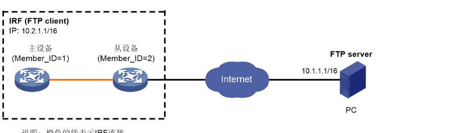
FTP客户端典型配置举例
1. 组网需求
· 主设备和从设备两台成员设备组成IRF。主设备的成员编号为1,从设备的成员编号为2。
· IRF作为FTP客户端,PC作为FTP服务器。
· IRF从PC上下载新的文件temp.bin,并将配置文件上传到PC进行备份。
· PC上已设置设备登录FTP服务器的用户名为abc,密码为hello12345。
2. 组网图
图1-2 FTP客户端典型配置组网图
3. 配置步骤
如果主设备和从设备剩余的内存空间不够,请使用delete /unreserved file–url命令删除部分暂时不用的文件后再执行以下操作。
配置前请确保IRF和PC之间路由可达,IP地址如图1-2所示,具体配置步骤略。
# 以用户名abc、密码hello12345登录FTP服务器。
<Sysname> ftp 10.1.1.1

Press CTRL+C to abort.

Connected to 10.1.1.1 (10.1.1.1).

220 WFTPD 2.0 service (by Texas Imperial Software) ready for new user

User (10.1.1.1:(none)): abc

331 Give me your password, please

Password:

230 Logged in successfully

Remote system type is MSDOS.

ftp>

# 将传输模式设置为binary,以便传输文件。

ftp> binary

200 TYPE is now 8-bit binary
# 将文件temp.bin从FTP服务器下载到IRF。
· 将文件temp.bin从FTP服务器下载到主设备存储介质的根目录下。
ftp> get temp.bin

local: temp.bin remote: temp.bin

150 Connecting to port 47457

226 File successfully transferred

23951480 bytes received in 95.399 seconds (251.0 kbyte/s)
· 将文件temp.bin从FTP服务器下载到从设备存储介质的根目录下。
ftp> get temp.bin slot2#flash:/temp.bin
# 将IRF的配置文件config.cfg上传到FTP服务器进行备份。
ftp> ascii

200 TYPE is now ASCII

ftp> put config.cfg back-config.cfg

local: config.cfg remote: back-config.cfg

150 Connecting to port 47461

226 File successfully transferred

3494 bytes sent in 5.646 seconds (618.00 kbyte/s)

ftp> bye

221-Goodbye. You uploaded 2 and downloaded 2 kbytes.

221 Logout.

<Sysname>
10.lldp
# 全局开启LLDP功能。
[ system-view](https://mail.163.com/js6/read/readhtml.jsp?mid=39:1tbiJxxxoWhTkLpiswAAsr&userType=browser&font=15&color=064977)

[Sysname] lldp global enable

[# ](https://mail.163.com/js6/read/readhtml.jsp?mid=39:1tbiJxxxoWhTkLpiswAAsr&userType=browser&font=15&color=064977)在接口GigabitEthernet1/0/1上关闭LLDP功能。

[ system-view](https://mail.163.com/js6/read/readhtml.jsp?mid=39:1tbiJxxxoWhTkLpiswAAsr&userType=browser&font=15&color=064977)

[[Sysname] interface gigabitethernet 1/0/1](https://mail.163.com/js6/read/readhtml.jsp?mid=39:1tbiJxxxoWhTkLpiswAAsr&userType=browser&font=15&color=064977)

[Sysname-GigabitEthernet1/0/1] undo lldp enable
11.Vpn实例
以下列拓扑(图1)所示,SW1、SW2、SW3级联,其中SW1、SW3为普通CE设备,SW2为MCE交换机。
SW2与SW1互联虚接口属于vpn-instance实例12中,SW2与SW3互联虚接口不属于任何vpn-instance实例。

用户希望实现属于VPN实例12中的业务,能够与非VPN实例的业务进行互访。及设备采用(图2)中所示的相关地址配置后,属于VPN实例12的SW1 1.1.1.1/32网段 能够与 非VPN实例的SW3 3.3.3.3/32网段进行通信。

**(1)**SW1、SW2、SW3根据(图2)中的相关IP地址进行配置部署。
**(2)**SW1配置去往3.3.3.3/32网段的静态路由;SW3配置去往1.1.1.1/32网段的静态路由
SW1配置
  #
  ip route-static 3.3.3.3 32 12.1.1.2
  #
SW3配置
  #
  ip route-static 1.1.1.1 32 23.1.1.2
  #
**(3)**SW2在实例12中配置去往1.1.1.1/32网段的静态路由;在非实例中配置去往3.3.3.3/32网段的静态路由
SW2配置
  #
  interface Vlan-interface12
  ip binding vpn-instance 12
  ip address 12.1.1.2 255.255.255.0
  #
  interface Vlan-interface23
  ip address 23.1.1.2 255.255.255.0
  #
  ip route-static vpn-instance 12 1.1.1.1 32 vpn-instance 12 12.1.1.1
  ip route-static 3.3.3.3 32 23.1.1.3
  #
**(4)**SW2在非实例路由表中增加去往1.1.1.1/32网段,下一跳为实例12中CE接口地址的静态路由
  SW2配置
  #
  ip route-static 1.1.1.1 32 vpn-instance 12 12.1.1.1
  #
**(5)**SW2在实例12路由表中增加去往3.3.3.3/32网段,下一跳为非实例中CE接口地址的静态路由
  SW2配置
  #
  ip route-static vpn-instance 12 3.3.3.3 32 23.1.1.3
  #
**(6)**在添加静态路由后,观察此时SW2路由表。
  <SW2>display ip routing-table 1.1.1.1 //非vpn实例路由表中去往1.1.1.1/32网段路由下一跳正常。
  Summary count : 1
  Destination/Mask  Proto  Pre Cost    NextHop     Interface
  1.1.1.1/32     Static 60 0      12.1.1.1    Vlan12

  <SW2>display ip routing-table vpn-instance 12 3.3.3.3 //vpn实例12路由表中去往3.3.3.3网段路由为空,静态路由未生效。
  <SW2>
**(7)**SW2在vpn实例12路由表中添加了去往3.3.3.3网段路由配置,增加public参数。
SW2配置
  #
  ip route-static vpn-instance 12 3.3.3.3 32 23.1.1.3 public
  #

  <SW2>display ip routing-table vpn-instance 12 3.3.3.3 //增加public后,相关静态路由生效。
  Summary count : 1
  Destination/Mask  Proto  Pre Cost    NextHop     Interface
  3.3.3.3/32     Static 60 0      23.1.1.3    Vlan23
**(8)**在SW1、SW3上互ping测试正常,及VPN实例业务与非VPN实例业务可以互通。
  <SW1>ping -a 1.1.1.1 3.3.3.3
  Ping 3.3.3.3 (3.3.3.3) from 1.1.1.1: 56 data bytes, press CTRL_C to break
  56 bytes from 3.3.3.3: icmp_seq=0 ttl=254 time=2.357 ms
  56 bytes from 3.3.3.3: icmp_seq=1 ttl=254 time=1.536 ms
  56 bytes from 3.3.3.3: icmp_seq=2 ttl=254 time=2.060 ms
  56 bytes from 3.3.3.3: icmp_seq=3 ttl=254 time=1.743 ms
  56 bytes from 3.3.3.3: icmp_seq=4 ttl=254 time=1.815 ms
  --- Ping statistics for 3.3.3.3 ---
  5 packet(s) transmitted, 5 packet(s) received, 0.0% packet loss
  round-trip min/avg/max/std-dev = 1.536/1.902/2.357/0.282 ms

  <SW3>ping -a 3.3.3.3 1.1.1.1
  Ping 1.1.1.1 (1.1.1.1) from 3.3.3.3: 56 data bytes, press CTRL_C to break
  56 bytes from 1.1.1.1: icmp_seq=0 ttl=254 time=2.568 ms
  56 bytes from 1.1.1.1: icmp_seq=1 ttl=254 time=1.729 ms
  56 bytes from 1.1.1.1: icmp_seq=2 ttl=254 time=2.024 ms
  56 bytes from 1.1.1.1: icmp_seq=3 ttl=254 time=1.951 ms
  56 bytes from 1.1.1.1: icmp_seq=4 ttl=254 time=1.859 ms
  --- Ping statistics for 1.1.1.1 ---
  5 packet(s) transmitted, 5 packet(s) received, 0.0% packet loss
  round-trip min/avg/max/std-dev = 1.729/2.026/2.568/0.288 ms
总结:
在VPN实例路由表中添加去往非VPN实例网段,及下一跳为公共路由表(非VPN实例路由表)下一跳CE地址的静态路由时,请添加public参数,已保证相关路由能够生效。
12.ospf
OSPF基本功能配置举例
1. 组网需求
· 所有的交换机都运行OSPF,并将整个自治系统划分为3个区域。
· 其中Switch A和Switch B作为ABR来转发区域之间的路由。
· 配置完成后,每台交换机都应学到AS内的到所有网段的路由。
2. 组网图
图1-8 OSPF基本功能配置组网图

3. 配置步骤
(1) 配置各接口的IP地址(略)
(2) 配置OSPF基本配置
# 配置Switch A。
<SwitchA> system-view

[SwitchA] router id 10.2.1.1

[SwitchA] ospf

[SwitchA-ospf-1] area 0

[SwitchA-ospf-1-area-0.0.0.0] network 10.1.1.0 0.0.0.255

[SwitchA-ospf-1-area-0.0.0.0] quit

[SwitchA-ospf-1] area 1

[SwitchA-ospf-1-area-0.0.0.1] network 10.2.1.0 0.0.0.255

[SwitchA-ospf-1-area-0.0.0.1] quit

[SwitchA-ospf-1] quit
# 配置Switch B。
<SwitchB> system-view

[SwitchB] router id 10.3.1.1

[SwitchB] ospf

[SwitchB-ospf-1] area 0

[SwitchB-ospf-1-area-0.0.0.0] network 10.1.1.0 0.0.0.255

[SwitchB-ospf-1-area-0.0.0.0] quit

[SwitchB-ospf-1] area 2

[SwitchB-ospf-1-area-0.0.0.2] network 10.3.1.0 0.0.0.255

[SwitchB-ospf-1-area-0.0.0.2] quit

[SwitchB-ospf-1] quit
# 配置Switch C。
<SwitchC> system-view

[SwitchC] router id 10.4.1.1

[SwitchC] ospf

[SwitchC-ospf-1] area 1

[SwitchC-ospf-1-area-0.0.0.1] network 10.2.1.0 0.0.0.255

[SwitchC-ospf-1-area-0.0.0.1] network 10.4.1.0 0.0.0.255

[SwitchC-ospf-1-area-0.0.0.1] quit

[SwitchC-ospf-1] quit
# 配置Switch D。
<SwitchD> system-view

[SwitchD] router id 10.5.1.1

[SwitchD] ospf

[SwitchD-ospf-1] area 2

[SwitchD-ospf-1-area-0.0.0.2] network 10.3.1.0 0.0.0.255

[SwitchD-ospf-1-area-0.0.0.2] network 10.5.1.0 0.0.0.255

[SwitchD-ospf-1-area-0.0.0.2] quit

[SwitchD-ospf-1] quit
4. 验证配置
# 查看Switch A的OSPF邻居。
[SwitchA] display ospf peer verbose
OSPF Process 1 with Router ID 10.2.1.1
Neighbors
Area 0.0.0.0 interface 10.1.1.1(Vlan-interface100)'s neighbors
Router ID: 10.3.1.1 Address: 10.1.1.2 GR State: Normal
State: Full Mode: Nbr is master Priority: 1
DR: 10.1.1.1 BDR: 10.1.1.2 MTU: 0
Options is 0x02 (-|-|-|-|-|-|E|-)
Dead timer due in 37 sec
Neighbor is up for 06:03:59
Authentication Sequence: [ 0 ]
Neighbor state change count: 5
BFD status: Disabled
Area 0.0.0.1 interface 10.2.1.1(Vlan-interface200)'s neighbors
Router ID: 10.4.1.1 Address: 10.2.1.2 GR State: Normal
State: Full Mode: Nbr is master Priority: 1
DR: 10.2.1.1 BDR: 10.2.1.2 MTU: 0
Options is 0x02 (-|-|-|-|-|-|E|-)
Dead timer due in 32 sec
Neighbor is up for 06:03:12
Authentication Sequence: [ 0 ]
Neighbor state change count: 5
BFD status: Disabled
# 查看Switch A的OSPF路由信息。
[SwitchA] display ospf routing
OSPF Process 1 with Router ID 10.2.1.1
Routing Table
Topology base (MTID 0)
Routing for network
Destination Cost Type NextHop AdvRouter Area
10.2.1.0/24 1 Transit 10.2.1.1 10.2.1.1 0.0.0.1
10.3.1.0/24 2 Inter 10.1.1.2 10.3.1.1 0.0.0.0
10.4.1.0/24 2 Stub 10.2.1.2 10.4.1.1 0.0.0.1
10.5.1.0/24 3 Inter 10.1.1.2 10.3.1.1 0.0.0.0
10.1.1.0/24 1 Transit 10.1.1.1 10.2.1.1 0.0.0.0
Total nets: 5
Intra area: 3 Inter area: 2 ASE: 0 NSSA: 0
# 查看Switch D的OSPF路由信息。
[SwitchD] display ospf routing
OSPF Process 1 with Router ID 10.5.1.1
Routing Table
Topology base (MTID 0)
Routing for network
Destination Cost Type NextHop AdvRouter Area
10.2.1.0/24 3 Inter 10.3.1.1 10.3.1.1 0.0.0.2
10.3.1.0/24 1 Transit 10.3.1.2 10.3.1.1 0.0.0.2
10.4.1.0/24 4 Inter 10.3.1.1 10.3.1.1 0.0.0.2
10.5.1.0/24 1 Stub 10.5.1.1 10.5.1.1 0.0.0.2
10.1.1.0/24 2 Inter 10.3.1.1 10.3.1.1 0.0.0.2
Total nets: 5
Intra area: 2 Inter area: 3 ASE: 0 NSSA: 0
# 在Switch D上使用Ping进行测试连通性。
[SwitchD] ping 10.4.1.1

Ping 10.4.1.1 (10.4.1.1): 56 data bytes, press CTRL_C to break

56 bytes from 10.4.1.1: icmp_seq=0 ttl=253 time=1.549 ms

56 bytes from 10.4.1.1: icmp_seq=1 ttl=253 time=1.539 ms

56 bytes from 10.4.1.1: icmp_seq=2 ttl=253 time=0.779 ms

56 bytes from 10.4.1.1: icmp_seq=3 ttl=253 time=1.702 ms

56 bytes from 10.4.1.1: icmp_seq=4 ttl=253 time=1.471 ms


--- Ping statistics for 10.4.1.1 ---

5 packet(s) transmitted, 5 packet(s) received, 0.0% packet loss

round-trip min/avg/max/std-dev = 0.779/1.408/1.702/0.323 ms
13.vrrp
VRRP单备份组配置举例
1. 组网需求
· Host A需要访问Internet上的Host B,Host A的缺省网关为10.1.1.111/24;
· 当Switch A正常工作时,Host A发送给Host B的报文通过Switch A转发;当Switch A出现故障时,Host A发送给Host B的报文通过Switch B转发。
2. 组网图
图1-9 VRRP单备份组配置组网图

3. 配置步骤
(1) 配置Switch A
# 配置VLAN2。
<SwitchA> system-view

[SwitchA] vlan 2

[SwitchA-vlan2] port gigabitethernet 1/0/5

[SwitchA-vlan2] quit

[SwitchA] interface vlan-interface 2

[SwitchA-Vlan-interface2] ip address 10.1.1.1 255.255.255.0
# 创建备份组1,并配置备份组1的虚拟IP地址为10.1.1.111。
[SwitchA-Vlan-interface2] vrrp vrid 1 virtual-ip 10.1.1.111
# 设置Switch A在备份组1中的优先级为110,高于Switch B的优先级100,以保证Switch A成为Master负责转发流量。
[SwitchA-Vlan-interface2] vrrp vrid 1 priority 110
# 设置Switch A工作在抢占方式,以保证Switch A故障恢复后,能再次抢占成为Master,即只要Switch A正常工作,就由Switch A负责转发流量。为了避免频繁地进行状态切换,配置抢占延迟时间为5000厘秒。
[SwitchA-Vlan-interface2] vrrp vrid 1 preempt-mode delay 5000
(2) 配置Switch B
# 配置VLAN2。
<SwitchB> system-view

[SwitchB] vlan 2

[SwitchB-Vlan2] port gigabitethernet 1/0/5

[SwitchB-vlan2] quit

[SwitchB] interface vlan-interface 2

[SwitchB-Vlan-interface2] ip address 10.1.1.2 255.255.255.0
# 创建备份组1,并配置备份组1的虚拟IP地址为10.1.1.111。
[SwitchB-Vlan-interface2] vrrp vrid 1 virtual-ip 10.1.1.111
# 设置Switch B在备份组1中的优先级为100。
[SwitchB-Vlan-interface2] vrrp vrid 1 priority 100
# 设置Switch B工作在抢占方式,抢占延迟时间为5000厘秒。
[SwitchB-Vlan-interface2] vrrp vrid 1 preempt-mode delay 5000
4. 验证配置
配置完成后,在Host A上可以ping通Host B。通过display vrrp verbose命令查看配置后的结果。
# 显示Switch A上备份组1的详细信息。
[SwitchA-Vlan-interface2] display vrrp verbose

IPv4 Virtual Router Information:

 Running Mode   : Standard

 Total number of virtual routers : 1

  Interface Vlan-interface2

   VRID       : 1          Adver Timer : 100

   Admin Status   : Up          State    : Master

   Config Pri    : 110         Running Pri : 110

   Preempt Mode   : Yes         Delay Time  : 5000

   Auth Type    : None

   Virtual IP    : 10.1.1.111

   Virtual MAC   : 0000-5e00-0101

   Master IP     : 10.1.1.1
# 显示Switch B上备份组1的详细信息。
[SwitchB-Vlan-interface2] display vrrp verbose

IPv4 Virtual Router Information:

 Running Mode   : Standard

 Total number of virtual routers : 1

  Interface Vlan-interface2

   VRID       : 1          Adver Timer : 100

   Admin Status   : Up          State    : Backup

   Config Pri    : 100         Running Pri : 100

   Preempt Mode   : Yes         Delay Time  : 5000

   Become Master   : 401ms left

   Auth Type     : None

   Virtual IP    : 10.1.1.111

   Virtual MAC   : 0000-5e00-0101

   Master IP     : 10.1.1.1
以上显示信息表示在备份组1中Switch A为Master,Switch B为Backup,Host A发送给Host B的报文通过Switch A转发。
Switch A出现故障后,在Host A上仍然可以ping通Host B。通过display vrrp verbose命令查看Switch B上备份组的详细信息。
# Switch A出现故障后,显示Switch B上备份组1的详细信息。
[SwitchB-Vlan-interface2] display vrrp verbose

IPv4 Virtual Router Information:

 Running Mode   : Standard

 Total number of virtual routers : 1

  Interface Vlan-interface2

   VRID       : 1          Adver Timer : 100

   Admin Status   : Up          State    : Master

   Config Pri    : 100         Running Pri : 100

   Preempt Mode   : Yes         Delay Time  : 5000

   Auth Type     : None

   Virtual IP    : 10.1.1.111

   Virtual MAC   : 0000-5e00-0101

   Master IP     : 10.1.1.2
以上显示信息表示Switch A出现故障后,Switch B成为Master,Host A发送给Host B的报文通过Switch B转发。
# Switch A故障恢复后,显示Switch A上备份组1的详细信息。
[SwitchA-Vlan-interface2] display vrrp verbose

IPv4 Virtual Router Information:

 Running Mode   : Standard

 Total number of virtual routers : 1

  Interface Vlan-interface2

   VRID       : 1          Adver Timer : 100

   Admin Status   : Up          State    : Master

   Config Pri    : 110         Running Pri : 110

   Preempt Mode   : Yes          Delay Time  : 5000

   Auth Type     : None

   Virtual IP    : 10.1.1.111

   Virtual MAC    : 0000-5e00-0101

   Master IP    : 10.1.1.1
以上显示信息表示Switch A故障恢复后,Switch A会抢占成为Master,Host A发送给Host B的报文仍然通过Switch A转发。
14.m-lag
此款交换机不支持m-lag
15.aaa用户
次内容涉及较多,您可以参考:https://www.h3c.com/cn/d_202501/2341078_30005_0.htm
或者
网络安全中AAA配置指南:认证、授权与计费的实现与故障排除(H3C S5130 交换机 系列)
16.mpls
此款交换机不支持mpls
17.BGP
此款交换机不支持bgp
18.dos攻击
此款交换机不支持dos攻击
19.irf
1 配置需求或说明
1.1 适用****产品系列
本案例适用于支持IRF2款型的V7交换机,具体型号是否支持,对堆叠的物理连线、模块是否有要求可以参考对应型号交换机操作手册中的IRF配置指导。在此以S5820V2交换机举例。
1.2 配置需求及实现的效果
由于网络规模迅速扩大,当前中心交换机(Device A)转发能力已经不能满足需求,需要另外增加一台设备Device B。现需要将两台设备配置IRF2堆叠,将网络转发能力提高一倍,并实现网络易管理、易维护。Device A和Device B分别使用自带的两个万兆口做堆叠口。也可以只用一个接口堆叠,根据实际情况而定。
2 组网图

3 配置步骤
3.1 配置IRF2
3.1.1 配置设备编号
# Device A保留缺省编号为1,不需要进行配置。同时,在Device B上将设备的成员编号修改为2。
<DeviceB> system-view  *//**进入系统视图*

[DeviceB] irf member 1 renumber 2  *//**将设备的成员编号修改为2*

Warning: Renumbering the switch number may result in configuration change or loss. Continue? [Y/N]:y

[DeviceB]
3.1.2 配置堆叠口
#将两台设备断电后,按组网图所示连接IRF链路,然后将两台设备上电。在Device A上创建设备的IRF端口2,与物理端口Ten-GigabitEthernet1/0/25、 Ten-GigabitEthernet1/0/26绑定,并保存配置。
<DeviceA> system-view  *//**进入系统视图*

[DeviceA] interface ten-gigabitethernet 1/0/25  *//**进入xg1/0/25接口*

[DeviceA-Ten-GigabitEthernet1/0/25] shutdown  *//**关闭接口*

[DeviceA-Ten-GigabitEthernet1/0/25] quit  *//**退出当前视图
*[DeviceA] interface ten-gigabitethernet 1/0/26  *//**进入xg1/0/26接口*

[DeviceA-Ten-GigabitEthernet1/0/26] shutdown  *//**关闭接口*

[DeviceA-Ten-GigabitEthernet1/0/26] quit  *//**退出当前视图*

[DeviceA] irf-port 1/2  *//**进入irf端口1/2*

[DeviceA-irf-port1/2] port group interface ten-gigabitethernet1/0/25  *//**将成员设备1的IRF物理端口Ten-GigabitEthernet1/0/25和IRF端口IRF-port2绑定*

[DeviceA-irf-port1/2] port group interface ten-gigabitethernet1/0/26  *//**将成员设备1的IRF物理端口Ten-GigabitEthernet1/0/26和IRF端口IRF-port2绑定*

[DeviceA-irf-port1/2] quit  *//**退出当前视图*

[DeviceA] interface ten-gigabitethernet 1/0/25  *//**进入xg1/0/25接口*

[DeviceA-Ten-GigabitEthernet1/0/25] undo shutdown  *//**开启接口*

[DeviceA-Ten-GigabitEthernet1/0/25] quit  *//**退出当前视图*

[DeviceA] interface ten-gigabitethernet 1/0/26  *//**进入xg1/0/26接口*

[DeviceA-Ten-GigabitEthernet1/0/26] undo shutdown  *//**开启接口*

[DeviceA-Ten-GigabitEthernet1/0/26] quit  *//**退出当前视图*

[DeviceA] save force  *//**保存配置*
# 在Device B上创建设备的IRF端口1,与物理端口Ten-GigabitEthernet2/0/25、Ten-GigabitEthernet2/0/26绑定,并保存配置。
<DeviceB> system-view  *//**进入系统视图*

[DeviceB] interface ten-gigabitethernet 2/0/25  *//**进入xg2/0/25接口*

[DeviceB-Ten-GigabitEthernet2/0/25] shutdown  *//**关闭接口*

[DeviceB-Ten-GigabitEthernet2/0/25] quit  *//**退出当前视图*

[DeviceB] interface ten-gigabitethernet 2/0/26  *//**进入xg2/0/26接口*

[DeviceB-Ten-GigabitEthernet2/0/26] shutdown  *//**关闭接口*

[DeviceB-Ten-GigabitEthernet2/0/26] quit  *//**退出当前视图*

[DeviceB] irf-port 2/1  *//**进入irf端口2/1*

[DeviceB-irf-port2/1] port group interface ten-gigabitethernet2/0/25  *//**将成员设备2的IRF物理端口Ten-GigabitEthernet2/0/25和IRF端口IRF-port1绑定*

[DeviceB-irf-port2/1] port group interface ten-gigabitethernet2/0/26  *//**将成员设备2的IRF物理端口Ten-GigabitEthernet2/0/26和IRF端口IRF-port1绑定*

[DeviceB-irf-port2/1] quit  *//**退出当前视图*

[DeviceB] interface ten-gigabitethernet 2/0/25  *//**进入xg2/0/25接口*

[DeviceB-Ten-GigabitEthernet2/0/25] undo shutdown  *//**开启接口*

[DeviceB-Ten-GigabitEthernet2/0/25] quit  *//**退出当前视图*

[DeviceB] interface ten-gigabitethernet 2/0/26  *//**进入xg2/0/26接口*

[DeviceB-Ten-GigabitEthernet2/0/26] undo shutdown  *//**开启接口*

[DeviceB-Ten-GigabitEthernet2/0/26] quit  *//**退出当前视图*

[DeviceB] save force  *//**保存配置*
# 激活DeviceA的IRF端口配置。
[DeviceA] irf-port-configuration active *//**激活DeviceA的IRF端口配置*
# 激活DeviceB的IRF端口配置。
[DeviceB] irf-port-configuration active *//**激活DeviceB的IRF端口配置*
#两台设备间将会进行Master竞选,竞选失败的一方将自动重启,重启完成后,IRF形成,系统名称统一为DeviceA
20.isis
此款交换机不支持isis
21.trunk口
Sys

Vlan 10

Quit

Vlan 20

Quit

interface Vlan-interface 10

ip address 192.168.10.1 24

quit

interface Vlan-interface 20

ip address 192.168.20.1 24

quit
interface GigabitEthernet 1/0/1

port link-type trunk

port trunk permit vlan all 或者 port trunk permit vlan 10 20

quit


暂无评论内容